
The idea came to me by experimenting with
intelligent RGB LED strips, that is equipped with a control microchip, like the
NEOPIXEL based on a WS2812B chip. The interesting thing is that just one bit is
enough to control numerous LEDs. The number of pixels is not limited by the
signal level, always retransmitted by each chip, but by the transmission speed.
On the web there are several libraries, I have tested
both the FastLED-master and the Adafruit_NeoPixel, both can drive various smart
led and controller chips. To measure the temperature I tried three types of
sensors but in the final version I used an LM35.
Of course this linear display is suitable for
displaying other physical quantities and the number of LEDs can easily be
increased.

The WS2812B
LEDs
They can be mounted on a flexible and adhesive
strip of printed circuit board, the appearance of which is shown in Figure 1.
The density is 60 LEDs per meter.
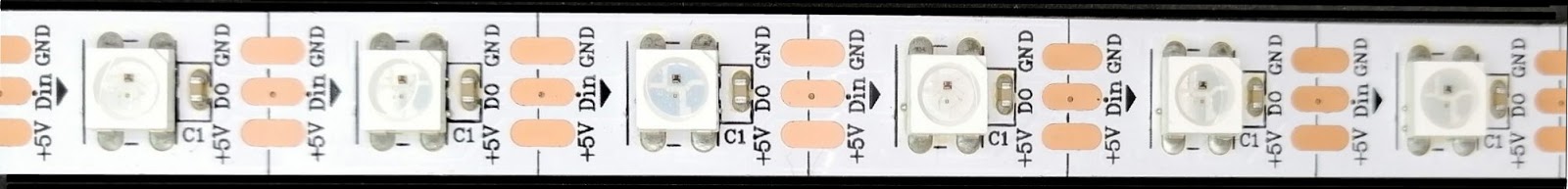 |
| Figure 1 - Typical appearance of a WS2812 strip.
The
chips, powered at + 5V with C = 100nF by-pass capacitor, are connected in
cascade according to the schematic shown in figure 2.
|
 |
| Figure 2 – Strip led wiring diagram. |
The serial communication protocol is
NRZ (Non Return to Zero) and the data is 24 bits, eight bits per color in the
order GRB (Green, Red, Blue) with the most significant bit first. In this way
up to 2^24 = 16777216 colors are realized. The bit rate can vary from 400 to
800 [kbits/s]. Figure 3 shows the diagrams of the packets transmitted and how
they are interpreted by the individual chips.
 |
| Figure 3 - Data transmission protocol. |
The first packet, sent by the MPU, is acquired
by the first D1 chip that retransmits the second and subsequent ones. The
second chip D2 acquires the second packet and retransmits the next ones, and so
on. At the end of the cycle, a pause of at least 50 µs resets the system.
Each LED consumes up to 20 mA, so 60 mA maximum
per chip. If I wanted to represent a light bar with 30 leds of white light,
that is with the three colors on, I would have a consumption of 1.8 A with
considerable dissipation and variation of current. In order to drastically
reduce the current I prefer to turn on only one led at a time using one of primary
colors RGB and also change its brightness.
My LM35 sensor prototype
It is an analog sensor, from National
Semiconductors / Texas Instruments, with output proportional to degrees Celsius
and a slope of 10 mV/°C, so the output signal is relatively low.

Its measurement range is from 2 to 150°C with a
power supply from 4 to 20 volts and, with particular circuits, it can measure
up to -55°C, figure 4 shows the sensor and pin layout.
If the Arduino ADC converter has Vref=5V
(default), the resolution is about 5mV, or 0.5°C. But the supply voltage is not
stable and varies significantly if Arduino is powered via USB or by Vin. If I
program analogReference (INTERNAL) the resolution becomes almost 1 mV because the internal reference of
the ADC is about 1.1V (from 1 to 1.2V) and is also much more stable than the
default mode. For
this reason I used this reference even if the display resolution is one
degree.
To measure the temperature of a house it
seems to me an
economic sensor that also requires a simple software. The scale of my display has 30 RGB
LEDs starting from 5 °C up to 34 °C. The schematic is that of figure 5.
 |
| Figure 5 - Electrical diagram of the thermometer. |
As a precaution, I powered the LED
strip with a separate regulator as, in the event of a fault more LEDs could be
lit simultaneously, the small controller on Arduino Nano could overheat and
even burn.
The average consumption of my
prototype is around 50 mA, this also because I only turn on
one led at a time and also reduced its
brightness. The power supply is similar to that used for Arduino, preferably
use voltages between 7.5 and 9 volts, even not stabilized.
I used an Arduino Nano because it is
compact and with a 0.1" pitch, necessary for prototyping matrix board. The
sensor is connected to pin A0 and I have connected a potentiometer on pin A1 to
calibrate the thermometer without modifying the program. For the prototype I
used a matrix board, as shown in figure 6. Notice at the top the sensor that
comes out of the box.
 |
| Figure 6 - Aspect of the components of the prototype. |
List of electronic components
component
|
description
|
component
|
description
|
R1
|
47 kW ±1% metal film
|
LD
|
RGB
strip LED type WS2812B
|
R2
|
220 W ±5%
|
Arduino
|
Arduino Nano board
|
Rp1
|
5 kW trimmer
|
U1
|
LM35 sensor
|
C1
|
100 µF,25V electrolytic
capacitor
|
U2
|
LM7805, 5V regulator
|
C2,C3,C4
|
100 nF ceramic capacitor
|
dissipator
|
Prototype construction
The simplest constructive solution is to buy
the led strip aluminum profile complete with its diffuser and to transfer on
it the thermometric scale numbers.
I used a "U" aluminum profile of
about 15x10 mm, 600 mm long for a total of 30 LEDs with a scale from 5 °C to 34
°C. The strip has a density of 60 LEDs per meter, so the pitch is about 16.7
mm.
At the end of the bar I fixed a small box
containing the electronics, while beside the led bar I glued an "L"
shaped profile of about 10x20 mm on which I drew the thermometric scale with a normographe,
then I painted it with a transparent varnish protection. This solution, quite
"do it yourself" is visible in the introductory photo. The writing
can also be done with a label printer or with self-adhesive numbers. The
version with the special profile and relative diffuser is also aesthetically
the most valid solution.
The program
For this program I used the Adafruit_NeoPixel
library (https://github.com/adafruit/Adafruit_NeoPixel) for the LED strip, because it is
simpler and more compact.
Nothing prevents you from using multiple LEDs
to enlarge the scale, updating the program on the #define NUM_LEDS 30 line and also modifying the control
of the LEDs. With some modifications we can use a scale in Fahrenheit and with
hardware and software interventions we can extend the scale even to negative
values.
The display resolution is one degree, so I
convert the temperature that is of float type to integer and address with this
the led to turn on.
I have used mostly only one of these leds and
with moderate intensity, for example:
pixels.Color (0, 0, 70);
it turns on one of the RGB colors (the blue LED,
in this case), with an intensity of only 70/255. This greatly reduces
consumption and does not disturb the eyes too much. Only at the ends of the
scale, to better highlight the exceeding of the limits, I use violet (red +
blue) and yellow (red + green) colors that require two LEDs, but I turn them on
only for one second every five. Reducing consumption also avoids heating the
sensor and distorting the measurement.
The led chip[0] is the one at the bottom: it is
lit blue for a temperature of 5 °C or flashes violet for lower temperatures.
The led chip[29] is the highest one and lights up red for a temperature of 34
°C or flashes yellow for higher temperatures.
My program turns on the LED chips based on the
following criteria:
·
Chip led[0] a violet flash of 1 second for T < 5°;
·
Chip led[0÷17] blue led on for 5°
≤ T <18°;
·
Chip led[18÷14] green led on for 18° ≤ T≤ 24°;
·
Chip led[25÷29] red led on for 25° ≤ T≤
34°;
·
Chip led[29] e yellow flash of 1 second for T >
34°C.
Of course it is very easy to change the limits
to better adapt them to personal wellbeing thresholds.
The function pixels.Color() sets the colors with three bytes
corresponding to the primary colors, respectively: R (Red) G (Green) B (Blue).
The intensity of the colors varies from 0,0,0 corresponding to the LEDs that
are all off (black) up to 255,255,255 for the three LEDs that are on (white).
Varying the intensity of the individual LEDs the displayed color varies. There
are on-line computers that simulate the color generated.
As already seen, the program reads the
potentiometer to make a correction of about -3° up to + 6°.
At the beginning I put VREF = 1050 mV, this
value is obtained by measuring the voltage with a digital voltmeter, otherwise
put VREF = 1100.
The code
/* program ArduTempLedLM.ino
Arduino strip led thermometer
use a LM35 or TMP35 as temperature sensor
Giovanni Carrera, rev. 11/05/2019 */
#include
<Adafruit_NeoPixel.h>
int Temp;
float NtomV;
const float VREF = 1050;//
in mV, this value can be read on VREF pin
#define PIN 2 // used for strip led data
#define NUMPIXELS 30 // number of leds in strip (5° to 34°C)
Adafruit_NeoPixel
pixels(NUMPIXELS, PIN, NEO_GRB + NEO_KHZ800);
#define DELAYVAL 500 // Time
(in milliseconds) to pause between pixels
void setup() {
Serial.begin(9600);
pixels.begin();// INITIALIZE NeoPixel strip
object delay( 500 );
analogReference(INTERNAL); // internal ADC
reference input = 1100V
NtomV = VREF/1023;// constant of conversion
into millivolts
}
void loop() {
int val = analogRead(A0);// read the LM35 sensor
float temperature = NtomV*val/10.0;// convert
to Celsius
val = analogRead(A1);// read the
potentiometer for T correction
float corr = NtomV*val/10.0 - 3;// adjusting
factor, about -3 to +6
temperature -= corr;// Temperature correction
Serial.print(" Temperature = ");
Serial.print(temperature,1);
Serial.println(" °C");
Temp = (int)temperature;
if (Temp < 5){
pixels.setPixelColor(0, pixels.Color(100,
0, 150));// bright violet color
pixels.show();
delay(1000);
pixels.setPixelColor(0, pixels.Color(0, 0,
0));
pixels.show();
}
else if (Temp < 18){// blue led for
T<18°
pixels.clear(); // Set all pixel colors to
'off'
// pixels.Color() takes RGB values, from
0,0,0 up to 255,255,255
pixels.setPixelColor(Temp-5,
pixels.Color(0, 0, 70));// moderately bright blue color
pixels.show();
}
else if (Temp >= 18 && Temp <=
24){
pixels.clear(); // Set all pixel colors to
'off'
pixels.setPixelColor(Temp-5,
pixels.Color(0, 70, 0));// moderately bright green color
pixels.show();
}
else if (Temp > 24 && Temp <=
34){
pixels.clear(); // Set all pixel colors to
'off'
pixels.setPixelColor(Temp-5,
pixels.Color(70, 0, 0));// moderately bright red color
pixels.show();
}
else {
pixels.setPixelColor(29, pixels.Color(150,
50, 0));// bright yellow color
pixels.show();
delay(1000);
pixels.setPixelColor(29, pixels.Color(0, 0,
0));
pixels.show();
}
delay(5000);
}
References
2)
“FastLED
Basic usage”, Daniel Garcia, https://github.com/FastLED/FastLED/wiki/Basic-usage,16 Aug 2017.
3)
“LM35
Precision Centigrade Temperature Sensors”, Texas Instruments, SNIS159H, August
1999–revised December 2017.
No comments:
Post a Comment