Translate

Showing posts with label PIC. Show all posts

Saturday, July 2, 2016

A PIC based 50MHz frequency meter

This project describes the realization of a sensible and accurate instrument to measure frequencies up to 50 MHz of signal amplitudes up to a few tens of millivolts. The instrument is small in size and can be battery powered, so it is a handheld instrument.

It is not very difficult to develop a microcontroller program capable of performing the frequency measurement of a periodic signal. The most critical and delicate circuit of a frequency meter is the input stage, which has the main task of amplifying weak signals to the maximum frequency that the microcontroller can process. The amplified signal must be squared and then brought to the logic levels of the microcontroller. Obviously, all these questions are useless if we need to measure only signals that are already at TTL level.

The circuit

After having examined and tested many circuits, I chose the circuit seen in Figure 2.
The transistors Q1 and Q2 form a wide bandwidth high to low impedance converter and the capacitor C1 removes the dc component. The core of the input circuit is the integrated circuit MC10116 which is responsible for amplifying and squaring the signal with switching times of few nanoseconds. This IC is a triple differential amplifier designed for use in sensing differential signals over long lines. This old chip is still produced and reachable on the market.
 Of course, these circuits have to work with very low impedances, thus require a relatively high supply current, approximately 100mA.
The transistors Q3 and Q4 serve to transform the differential output of MC10116 in a single ended signal with TTL levels.
For the measurement of the frequency and for the driving of the LCD display I used a PIC16F628, an extremely diffuse PIC. Power is supplied by four 1.5V batteries. To get the 5V, a low-dropout regulator is employed.

The complete diagram of the system is shown in Figure 3.
The figure 4 shows the inside of my prototype, the PIC microcontroller is not visible because covered by the display, which has a row of 16 characters, but it is seen by its controller as two rows of 8.
The arrangement of all the components on the card is shown in figure 5. A small heat sink is used for the regulator because the current consumption is about 100 mA.

The crystal accuracy

The typical frequency tolerance of a quartz crystal is ±10 to ±100 ppm (part per million), and its frequency/temperature coefficient depends upon the crystal cut, for a 32,768 Hz xtal it is about -0.04 ppm/°C but on other cuts it reaches 5 ppm/°C. Although at 50,000,000 Hz we have the resolution of 1 Hz, the error due to the accuracy of quartz and its stability with temperature is much greater. The more accurate frequency counters have a TCXO (Temperature Compensated Crystal Oscillator) and the best stability is achieved from OCXO (Oven Controlled Crystal Oscillator).
It would be possible to make even the accuracy correction of quartz, usually in the order of +/- 50 ppm. A higher accuracy is obtained with an external high-stability quartz oscillator.
By comparing the reading with that of a precision frequency counter or reading a very precise frequency reference, such as that of the carriers of certain radio stations, you can correct the frequency by setting the final count counts. I made the calibration, correcting particularly the delays introduced by the program instructions execution.

The program

The PIC Timer#1 is used as counter on PB6 digital input, with interrupt on overflow. Every Timer#1 overflow the variable overc is increased by the interrupt routine. The Timer#0 is programmed to generate an interrupt every 8 ms, for a time base of one second 125 ticks are needed. Every second is calculated the total count, it is also made a correction, and displayed on the LCD.
The number of overflows of the 16-bits register of Timer#1, stored in overc, represents the most significant word, while the content of the Timer # 1, stored in count, is the least significant word of the final count. For example, for a frequency of 50,000,000 Hz the variable counts = hex 02 FA F0 80, so overc = hex 02 FA and count = hex F0 80.
The correction tries to reduce delays xx of the overflow interrupt routine, in fact it subtracts from the counts the term xx * overc, in this case xx = 46.
I compiled my program  in mikroPascal PRO rev.7 for PIC (mikroElektronika, www.mikroe.com). The length of the code is longer than 2k bytes, so it can’t be compiled with the free version of the compiler and I provide also the hex file to the PIC programmer. With recent versions of the compiler you must make some modification to the display pin definitions.
You can download the files from: https://github.com/ArduPicLab/frequencymeter

References
1)      “MC10116 – Triple line receiver”, Motorola, Inc. 1996.
2)      “AN MSI 500 MHz FREQUENCY COUNTER USING MEeL AND MTTL”, Jon M. Delaune, Motorola application note AN-581.
3)      “DIY KIT 95. 50MHZ 8-DIGIT FREQUENCY METER”
4)      “Fundamentals of Quartz Oscillators”, Hewlett Packard Application Note 200-2

Sunday, June 26, 2016

A 16 channels 12 bits acquisition system

Today many microcontrollers have one or two 10-bit or more built in AD converters with a multi-channel multiplexer, but the quality of conversion is rather poor because of the considerable background noise always present together with a low linearity. So, I think it will be useful the proposed system, since the components are still readily available and the results obtained are at a professional level.
However I think that even with a different ADC hardware, the software used is still valid, as a result of years of experience. The system design is a front end controlled remotely via a serial link that can be the standard RS232 / RS422, or wireless.

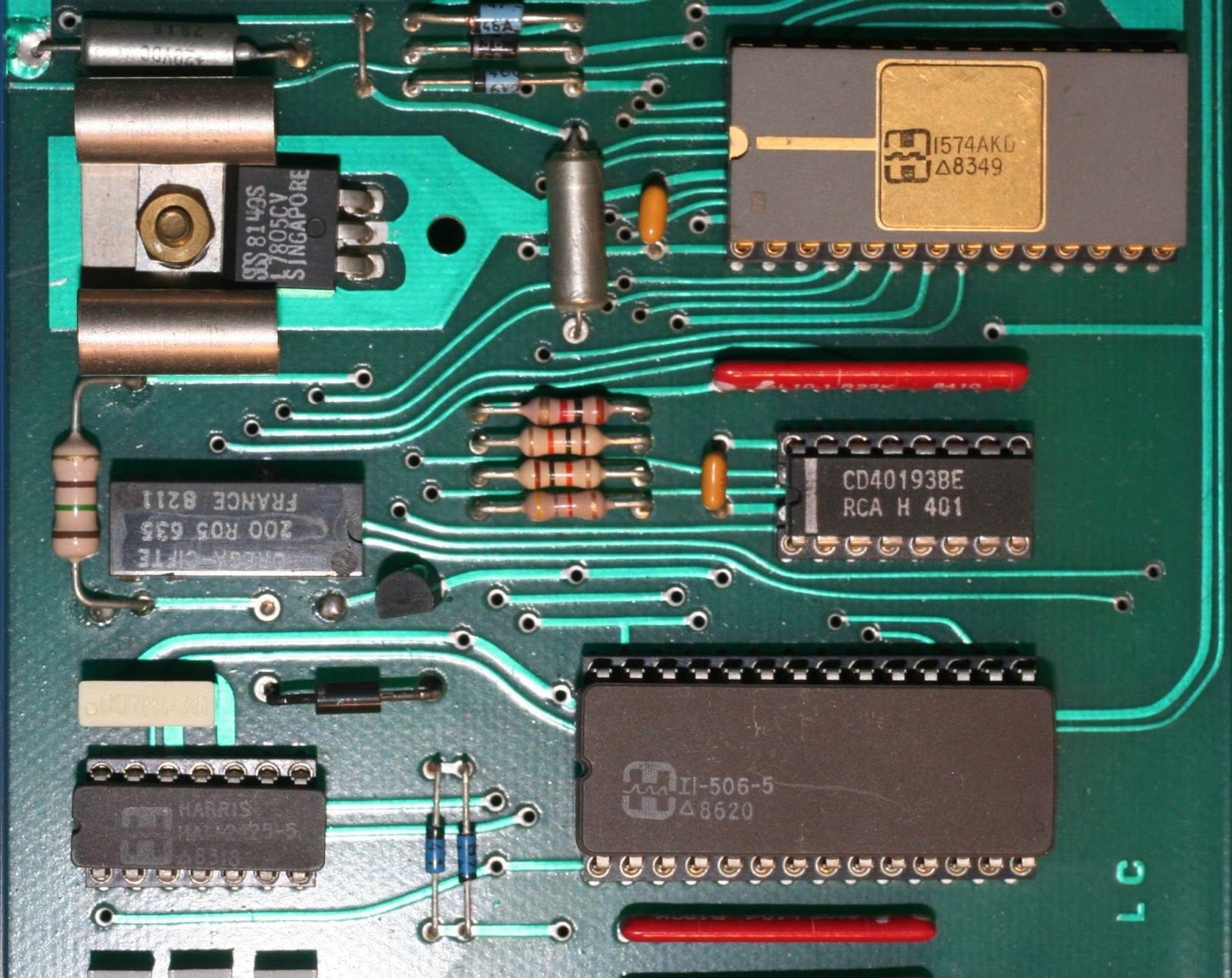
In the years '80 I had designed a digital acquisition system (DAS16) based on the classic 12 bit analog to digital converter AD574, from Analog Devices. In addition to this device I was using a 16-channel multiplexer HI506 followed by a sample and hold circuit based on HA2425. The diagram of this board is visible in Figure 1.  I used it with various computers and microcontrollers, including the IBM PC, through the parallel interface, the Apple II with a my own interface card and finally, with a 80196 microcontroller. The system remained unused for several years, then in 2007, I designed a new controller based on a PIC to interface it with computers or tablets via a serial interface. The system was slower, but the parallel interface was disappearing from laptops.


The counter CD40193 can be used to load the starting address of the channel and then to generate the subsequent scanning addresses by means of a simple clock.
The two 74LS367, hex buffers with 3-state outputs, are required to create an 8 or 4 bit data bus from the 12 bits parallel output of the converter. The 4-bit bus, was necessary for the printer interface of the first PC, which had not yet become an 8-bit bidirectional bus (standard IEEE 1284).
The board must be powered at +/- 15V and a LM7805 is mounted on it to power logic devices. A reed relay (K1) is used to change the range from +/- 5V to +/- 10V, under software control. A 31 pins male connector (DIN 41617) was used in my board.

The DAS controller

I used a PIC16F73 because already available. The scheme is shown in Figure 3. I used a 18.432 MHz quartz because suitable for the exact generation of the UART baud rate. This component is easily found in the old PC serial cards.
Since microcontrollers don’t have a great memory, I could not use a large ram buffer that allows a high sampling rate. Then the achievable sampling frequency is limited by the maximum baud rate of the UART. The program, according also to the channels to be scanned, check if the required sample period is valid for data transmission.
Figure 4 shows the arrangement of the components of the PIC DAS controller. A 32-pin DIN connector connects this board with the DAS16. Note the double-dip switch that is used to set the 4 possible baud rates (on on: 9600, on off: 19200, off on: 57600, off off: 115200). An external push button is used to start the acquisition and a red LED lights up during the whole time of the acquisition.

This system, with the software provided, can acquire up to 16 analog channels at the maximum frequency of 1kHz, for one channel, at a baud rate of 115200 b/s. The time required for one scan of 16channels is about 0.4 milliseconds plus the time to transmit the data. The following table gives an idea of the possible sampling frequency limits.
channels
baud rate
Ts [ms]
Fs max. [Hz]
1
115200
1
1000.00
16
115200
10
100.00
1
9600
10
100.00
16
9600
103
9.71
With a baseline period of 1 ms, the maximum sampling period is 255 ms which corresponds to a minimum frequency of about 3.92 Hz. If you want to use lower frequencies, with simple changes (TMR0 = 76 instead of 238) you can use a basic period of 10 ms, as it was in the first version of the program.
As the project is not new but dates back to 2007, it is used standard serial interface RS232. Today you could use a TTL / USB serial adapter or a serial bluetooth module to connect to PCs, tablets or smartphones.

Figure 5 shows the connections between the boards.

The program
I modified and improved the program I had written in 2007 with a new version of the compiler and improving the interpretation of the command string. I had some problems because the memory limits of the PIC16F73, using about 92% of PIC flash memory and 96% of ram,  but I did not want to change the CPU with the newer ones.
All acquisition parameters, ie the initial and final channel of the scan, the full scale (+/- 5 or 10V) and the sampling frequency can be set by the computer by means of a command string. The acquisition start pressing the appropriate button or sending an ‘A’ by the terminal. The program checks whether the required sample period is compatible with the number of channels and the UART baud rate, in case of incompatibility a warning is printed on the terminal and a new corrected command string will be necessary.
The configuration string is of the form:
“$ci,cf,BPm,ns,fs*”
  Where:
ci = start channel (0..15);
cf = last channel of the scan (0..15);
BPm = Base Period multiplier (1..255), the Base Period = 1 [ms];
ns = Number of samples (1.. 65535);
fs = ADC full scale (5 or 10) bipolar.
The command string header is ‘$’ and the end is ‘*’, for example, the command string : “$0,5,50,2048,5*” is interpreted as a scan from channel 0 to channel 5 with a sampling period of 50ms, 2048 samples with a +/- 5V range.
If the parameters are okay, the system print the message 'Push Start Button or write A to start', otherwise one of the following messages will be printed:
Errors on configuration string !!
If we use a sample period too short  compared to the baud rate and the number of channels, the following message will printed:

Ts is incompatible with baud rate !!
Ts must be greater than xxxx [us]

Where xxxx = tscan+ttx is the minimum sampling period to be used, in microseconds.
In both cases a new correct string will be sent. In the case of the example above, the system respond to the command string with the message:

Initial Ch = 0, Final Ch = 5, +/- F.S. [V] = 5
Ts [ms] = 50, Samples = 2048
Push Start Button or write A to start

This information is useful for the program that will process the data, so it may be saved on the captured file. After pressing the button, or sending ‘a’, we can read the transmitted data:
DATA
  -720  -481  -708  -505  -730  -488
  -691  -464  -683  -490  -708  -488
……
The rows with the channel scans are preceded by the word 'DATA'. During acquisition the led is on and, at the end, the system is waiting for a new acquisition with the same parameters. If you want to change them, a reset button or turning off and turning on the power switch will restart the system.
The next lines, one for each scan, contain the data in a fixed format, six characters (including the sign) per channel, expressed in [mV].
On PC or tablet, you can use a terminal emulation program capable to save the received data to an ASCII file, I used RealTerm on Windows 7.
I compiled the new program  in mikroPascal PRO rev.6.6 for PIC (mikroElektronika, www.mikroe.com). The length of the code is greater than 2k bytes, so it can’t be compiled with the free version of the compiler and I provide also the hex file for the PIC programmer.

Wednesday, September 30, 2015

Tiny Accelerometers Acquisition System

By Giovanni Carrera - http://ardupiclab.blogspot.it/

The aim of this project is to realize a small acquisition system of a triaxial accelerometer connected via serial interface to a pc or tablet, using an appropriate adapter as TTL/USB or TTL/Bluetooth.
However, this system can also be used for other sensors with the same output range.

The Circuit
I used the PIC microcontroller 16F688, with minor modifications to the firmware you can use another microcontroller with one UART, three channels ADC and two digital bit.
For the CPU clock I used a 18.432 MHz quartz, the reason is that this frequency is particularly suitable for serial baud rate generation. You can find it easily in a RS232 board for PC.
The following figure shows the schematic of this project.
A quadruple dip switch allows you to set the sample rate and the range of accelerometers. To optimize the input range of the ADC, I used the TL431 regulator as adjustable reference source with a good thermal stability. As indicated in the scheme, the trimmer must be adjusted for a 2.80 output voltage, the same output range of the sensors.  The serial out is TTL 5V level. The following picture shows the arrangement of the components on the board of my prototype.

 The card with the accelerometer module has been removed to better see the mounted components, while the photo below shows the accelerometer module mounted. I used the module DC-SS009 made by Sure Electronics, but you can use an equivalent board. It utilizes the chip MMA7260QT from Freescale Semiconductor.
The J3, 4 pin, connector is used to acquire external analog signals, in this case the accelerometer module must be removed. RS1 is a quadruple sil resistor array. For the voltage divider I used 1% tolerance resistors and a 20 turns trimpot.
For a pc connection I used a TTL to USB adapter, which also powers the system. Are particularly suitable even those contained in the same USB connector, you have to install its driver on the PC.

The software
I set prescaler of Timer#0 to 256 and TMR0= 76, so it overflows every 180 counts. With these settings and with the quartz used, you get an interrupt every 10 ms (f = 100 Hz). This is the base period to generate the sampling periods with appropriate multipliers.
Two dip switches (dip1, dip2) are used to select the sampling period multiplier in order to obtain the frequencies of 5, 10, 50 and 100 Hz. The other two dip switches set the full scale of accelerometers(1.5, 2, 4, 6 g) by acting directly on the chip MMA7260QT and are not controlled by the program.
The serial output is ASCII coded with 38400 baud rate. Every row contains the numbers (0-1023) corresponding to the accelerometers X, Y, Z.  At first, after the reset, the device transmits the selected period in milliseconds .
To get the data in physical quantity (g) it is necessary to make a calibration using the acceleration of gravity, therefore, the conversion may be done on the pc.  I compiled my program  in mikroPascal PRO for PIC (mikroElektronika, www.mikroe.com).
The source and compiled files (hex format) can be downloaded at:


Bibliography
1)      “3 Axis Acceleration Sensor Board User’s Guide”, DC-SS009, Sure Electronics, 2007.

2)      “±1.5g - 6g Three Axis Low-g Micromachined Accelerometer”, MMA7260QT, Freescale Semiconductor, 2007.


Thursday, August 13, 2015

A very simple way to power Arduino

A simple and inexpensive solution is to use a 'mobile power bank', which is now widely available at low cost (from 5 €). The capacity of these systems is very high, almost always greater than 2000mAh, although some Chinese manufacturers print values ​​little true, as is the case for the batteries.
It is used to give energy to our smartphone or tablet, in cases in which our cellular battery is discharged or we can’t use the electricity grid. These devices incorporate, in a small volume, one or more rechargeable polymer battery, a charger (5V to 4.2V) and a step-up switching power supply to generate the 5V output from 3.6 V battery.
Normally it has two USB connectors female: output type A to power the phone or tablet and a micro USB for charging the internal battery, it connects to a normal power supply 5-5,5V 1 or 2 A, which is now a standard for the last generation mobile phones o tablets.
Usually they are provided of one or more cables to adapt to phones and tablet, typically with the micro USB or with standard iPhone connector. With the cable terminated with USB Micro, we can supply different cards, including Arduino Due, Yun, Nano and Teensy.
To power Arduino Uno we need a common USB cable A / B USB, like that used for printers.
This type of power supply is particularly suitable for portable and very compact systems, and it has an operating time of several hours. I use these devices for some years.

The photo below shows an example of an application with Arduino Yun.
With the experience of a few years of use of the power banks, may I suggest that you preferably use those that have a power switch. They cost more but do not have an internal consumption that significantly reduces battery life. In some cases I measured a battery discharge current of about 2 mA without any external load.