The changes hw & sw are described to adapt
an I2C LCD display to ESPs or other microcontrollers powered at 3.3V.
An LCD display, compatible with the Hitachi
HD44780 controller, connected with 4 data bus bits, requires a minimum of 6
GPIO pins. Using a special module it is possible to use only two pins with I2C
bus and several Arduino libraries are also available for it. I used the
LiquidCrystal_I2C [1] which, although the Arduino compiler prints a warning
message that is for AVRs, has also worked well for ESP.
Figure 1 shows the module I used, made
specifically to be soldered directly to a common alphanumeric LCD display.
 |
| Figure 1 |
Before soldering it, check the position of the
pins and compare them with those in the figure. The complete scheme of this module is shown in
figure 2.
 |
| Figure 2 |
This module uses the PCF8574 chip, 8-bit I/O
expander with I2C bus, which connects to the 4-bit bidirectional bus display.
It also controls the display backlighting via PA3 and the transistor Q1, with
the jumper inserted.
I preferred to use an LCD display because it
consumes much less than an Oled, and my goal was to operate the ESP in deep
sleep mode and power everything on battery power.
For these reasons I used a display without
backlight, with a 14-pin connection and therefore I had to cut the two pins 15
and 16 of the module in order to insert it.
I/O level
adapting
No problem for interfacing with Arduino Uno and
similar with 5V power supply and I/O signals with the same level.
The ESP8266/32 have 3.3V power supply and GPIO
levels are not 5V tolerant, so the first thing I looked at is the level of the
output signals.
The characteristic of I2C is that every device
on the bus must connect to both the clock signal (SCL) and the data signal
(SDA) via open-drain (or open-collector) output drivers. This means that
controllers can only bring the output to zero and that pull-up resistors must
be used to return to high level.
So it is not necessary to use a level adapter,
but to check if the pull-up resistors are mounted and
at what voltage. As can be seen in the diagram, these are present and connected
to the 5V.
If we want to connect this module to ESP or
other 3.3V powered microcontrollers, we have to unsolder the 4.7 kW resistors R5 and R6. Since my intention is also
to consume less current, I also removed R1 (1 kW) of the useless red LED1 and R7, near the
transistor Q1. Figure 3 shows the positions of the four resistors to be
unsoldered. If you want to use a backlit display, R7 should not be removed.
 |
| Figure 3 |
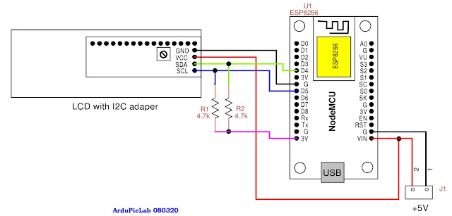
Obviously two 4.7 kW resistors connected to + 3.3V must
be mounted externally, as in figure 4.
Then we have to set the I2C address using the
three jumpers near the trimmer that regulates the contrast. The three 10 kW resistors R2, R3, R4 are pull-ups
of the three bits A0, A1, A2 of address I2C of the PCF8574. The other four
bits, of the seven I2C address bits, are fixed and have the following values:
|
0
|
1
|
0
|
0
|
A2
|
A1
|
A0
|
If we do not solder the jumpers: A0 = A1 = A2 =
1, so the address will be 0x27, each jumper will produce a zero as it is
connected to ground.
Figure 4 shows the connections of the LCD
display complete with adapter with a NodeMCU card with ESP8266. I used pin D5
(GPIO14) for SCL and D4 (GPIO2) for SDA. |
| Figure 4 |
Figure 5 shows the two-line 16-character
display to which the modified module has been soldered. Consumption is around 2
mA.
 |
| Figure 5 |
Figure 6 shows the display under test, made
with a breadboard for the resistors and the connection wires with the NodeMCU
board.
Anyone wishing to mount a display with
backlighting must, in addition to not remove the R7 and not cut pins 15 and 16,
also enter the instruction that lights the display LEDs:
lcd.backlight ();
In the next realization I intend to use only
the ESP-V12f module, always to reduce power consumption.
 |
| Figure 6 |
The test
program
To test the system I wrote a simple program
that prints the seconds on the second line.
To avoid overlapping the text on the previous
print, I first print a row of spaces.
The library must be configured with the
instruction:
LiquidCrystal_I2C lcd (0x27,16,2);
Which allows you to set the display address
(0x27), the number of columns and rows.
If more than one LCD display is used, jumpers
must be set to create a different address.
On the ESP8266 almost all I/O bits can be used
for the I2C interface. The LiquidCrystal_I2C library allows you to assign the
two pins using the function:
lcd.begin (SDA, SCL);
Below is the list of the test programs.
/*program ESP_LCD.ino,
for test
ESP8266 with a I2C LCD display
Giovanni Carrera, rev. 22/02/2020 */
#include
<Wire.h>
#include
<LiquidCrystal_I2C.h>
#define SDA 2 // D4 for NodeMCU
#define SCL 14 // D5 for NodeMCU
char bline[17] =
" ";// blank
line
int sec = 0;
unsigned long cmilli,
pmilli;
const int deltat =
1000;
LiquidCrystal_I2C
lcd(0x27,16,2); // set the LCD address to 0x27 for a 16 chars and 2 line
display
void setup(){
Wire.begin (SDA, SCL);// pin used for I2C bus
lcd.begin(SDA, SCL);// for ESP8266
lcd.setCursor(0,0);// lcd.setCursor(col, row)
lcd.print("ESPV12 LCD test"); //
Print intro message
}
void loop(){
cmilli = millis();
if (cmilli - pmilli >= deltat) {
pmilli = cmilli;
lcd.setCursor(0, 1);
lcd.print(bline);// clear the second row
lcd.setCursor(0, 1);
lcd.print(sec);// print seconds on the
second row
sec++;
lcd.setCursor(6, 1);
lcd.print("seconds");
}
}
References
1. “LiquidCrystal I2C”, Marco Schwartz, https://github.com/marcoschwartz/LiquidCrystal_I2C/archive/master.zip

No comments:
Post a Comment