This project describes the realization of a
sensible and accurate instrument to measure frequencies up to 50 MHz of signal
amplitudes up to a few tens of millivolts. The instrument is small in size and
can be battery powered, so it is a handheld instrument.
It is not very difficult to develop a microcontroller
program capable of performing the frequency measurement of a periodic signal.
The most critical and delicate circuit of a frequency meter is the input stage,
which has the main task of amplifying weak signals to the maximum frequency
that the microcontroller can process. The amplified signal must be squared and
then brought to the logic levels of the microcontroller. Obviously, all these
questions are useless if we need to measure only signals that are already at
TTL level.
The circuit
After having examined and tested many circuits,
I chose the circuit seen in Figure 2.
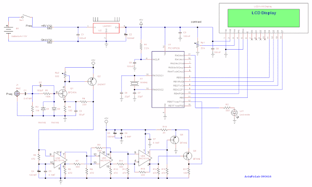
The transistors Q1 and Q2 form a wide bandwidth
high to low impedance converter and the capacitor C1 removes the dc component. The
core of the input circuit is the integrated circuit MC10116 which is
responsible for amplifying and squaring the signal with switching times of few
nanoseconds. This IC is a triple differential amplifier designed for use in
sensing differential signals over long lines. This old chip is still produced
and reachable on the market.
Of
course, these circuits have to work with very low impedances, thus require a
relatively high supply current, approximately 100mA.
The transistors Q3 and Q4 serve to transform
the differential output of MC10116 in a single ended signal with TTL levels.
For the measurement of the frequency and for
the driving of the LCD display I used a PIC16F628, an extremely diffuse PIC.
Power is supplied by four 1.5V batteries. To get the 5V, a low-dropout
regulator is employed.
The complete diagram of the system is shown in
Figure 3.
The figure 4 shows the inside of my prototype,
the PIC microcontroller is not visible because covered by the display, which has
a row of 16 characters, but it is seen by its controller as two rows of 8.
The arrangement of all the components on the
card is shown in figure 5. A small heat sink is used for the regulator because the
current consumption is about 100 mA.
The crystal accuracy
The typical frequency tolerance of a quartz
crystal is ±10 to ±100 ppm (part per million), and its frequency/temperature coefficient
depends upon the crystal cut, for a 32,768 Hz xtal it is about -0.04 ppm/°C but
on other cuts it reaches 5 ppm/°C. Although at 50,000,000 Hz we have the
resolution of 1 Hz, the error due to the accuracy of quartz and its stability
with temperature is much greater. The more accurate frequency counters have a TCXO
(Temperature Compensated Crystal Oscillator) and the best stability is achieved
from OCXO (Oven Controlled Crystal Oscillator).
It would be possible to make even the accuracy
correction of quartz, usually in the order of +/- 50 ppm. A higher accuracy is
obtained with an external high-stability quartz oscillator.
By comparing the reading with that of a
precision frequency counter or reading a very precise frequency reference, such
as that of the carriers of certain radio stations, you can correct the
frequency by setting the final count counts. I made the calibration, correcting particularly
the delays introduced by the program instructions execution.
The program
The PIC Timer#1 is used as counter on PB6 digital
input, with interrupt on overflow. Every Timer#1 overflow the variable overc is increased by the interrupt
routine. The Timer#0 is programmed to generate an interrupt every 8 ms, for a
time base of one second 125 ticks are needed. Every second is calculated the
total count, it is also made a correction, and displayed on the LCD.
The number of overflows of the 16-bits register
of Timer#1, stored in overc, represents the most significant word, while the content of the Timer #
1, stored in count, is the least significant word of the final count. For example, for a
frequency of 50,000,000 Hz the variable counts = hex 02 FA F0 80, so overc = hex 02 FA and count = hex F0 80.
The correction tries to reduce delays xx of the
overflow interrupt routine, in fact it subtracts from the counts the term xx *
overc, in this case xx = 46.
I compiled my program in mikroPascal PRO rev.7 for PIC
(mikroElektronika, www.mikroe.com). The length of the code is longer than 2k
bytes, so it can’t be compiled with the free version of the compiler and I
provide also the hex file to the PIC programmer. With recent versions of the
compiler you must make some modification to the display pin definitions.
References
1)
“MC10116
– Triple line receiver”, Motorola, Inc. 1996.
2)
“AN
MSI 500 MHz FREQUENCY COUNTER USING MEeL AND MTTL”, Jon M. Delaune, Motorola
application note AN-581.
3)
“DIY
KIT 95. 50MHZ 8-DIGIT FREQUENCY METER”
4)
“Fundamentals
of Quartz Oscillators”, Hewlett Packard Application Note 200-2


No comments:
Post a Comment